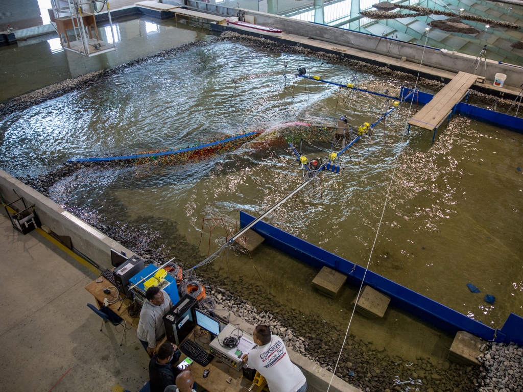
CSIR coastal and hydraulics laboratory
The coastal and hydraulics laboratory is an 11 000m2 facility that houses infrastructure for both 2D and 3D physical model studies. It has three large wave basins (32 m x 54 m x 1.5 m, 32 m x 60 m x 1 m, 32 m x 40 m x 1.5 m) for 3D modelling, with removable walls to create a larger wave basin (up to 115 m long), if needed. Waves can be generated by nine 4 m multi-element rack and pinion wave generators from HR Wallingford, which are controlled using HR Wallingford software. Steel and wooden boundary walls act as guides to control wave direction, and the system is equipped with a dynamic wave absorption feature.
The system can produce regular or irregular wave patterns and various wave forms, including long- and short-crested waves. It can also produce random wave forms defined by user inputs, and waves can be created in any direction within a 30° arc.
3D modelling usually focuses on scales from 1:40 to 1:60, but the facility can produce accurate models up to 1:120 for especially large projects.
The facility includes two wave flumes (4 m x 32 m x1 m, 12 m x 32 m x1 m) for quasi-3D modelling and two wave flumes (both 1 m x 32 m x 1 m, one glass and one concrete) for 2D modelling. The wave flumes use a single paddle wave maker (0.75 m paddle), also from HR Wallingford, and are capable of producing both regular and irregular wave shapes.
2D modelling is mostly used to study a design in cross-section and ranges in scale from 1:20 to 1:40.
The laboratory can measure wave amplitudes, direction, and force as well as propagation and agitation; vessel motions and response; mooring forces; wave run-up and overtopping; slope and breakwater stability; and force and pressure measurements.
Wave measurements
Wave measurements are conducted using either capacitance wave gauges (up to 0.5 mm accuracy), or the CSIR’s proprietary keofloat system (up to 0.2 mm accuracy). The keofloat system is most accurate for waves smaller than 5 mm and is useful for up to 20 mm waves. Above that, the capacitance wave gauges are the most accurate.
Capacitance wave gauges rely on electrical capacitance data to measure wave height and direction, while the keofloat system uses videography to measure the vertical movement of floating probes with sub-pixel accuracy. To measure wave direction, groups of keofloat probes are employed.
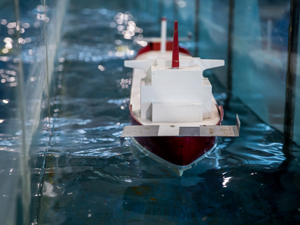
Vessel motions
The laboratory constructs its model vessels to scale, which are proportional in both size and load weight to full-size ships and have the same centre of gravity and moment of inertia around both horizontal axes. This ensures that the models behave in the same way as their full-size counterparts when being tested. Model vessels are calibrated to ensure both the roll and pitch periods are correct before being used in tests.
Once the model ships are built, their movements can be measured using the CSIR-developed keoship system. Similar to the keofloat system, this uses videography and a processing algorithm to record ship motions at sub-pixel accuracy and convert that data into information on all six types of ship movement (heave, surge, sway, pitch, roll and yaw). The first three degrees of freedom refer to the directional movement of the ship and have an accuracy of 0.1 mm, while the last three degrees of freedom refer to rotational movement around all three ship axes and have an accuracy of 0.04° (roll) and 0.01° (pitch and yaw).
Mooring forces
Measuring strain on mooring lines is vitally important when modelling a port or harbour. To achieve this, the laboratory uses strain gauges attached to mooring lines, which provide an output in Newtons of force with an accuracy of up to 5 mN. The mooring lines themselves are calibrated to provide the correct amount of resistance and elasticity. The keoship system can also be used for this measurement, which is more convenient than using strain gauges but slightly less accurate (10–30 mN).
Pressure and force measurements
Pressure on walkways and caissons (watertight retaining structures for underwater construction) can also be measured using pressure gauges or force transducers.
Overtopping
Wave overtopping occurs when water splashes over a breakwater and can cause damage through flooding or endanger human life. The laboratory measures overtopping for coastal structures in litres per second per metre-width of the structure.
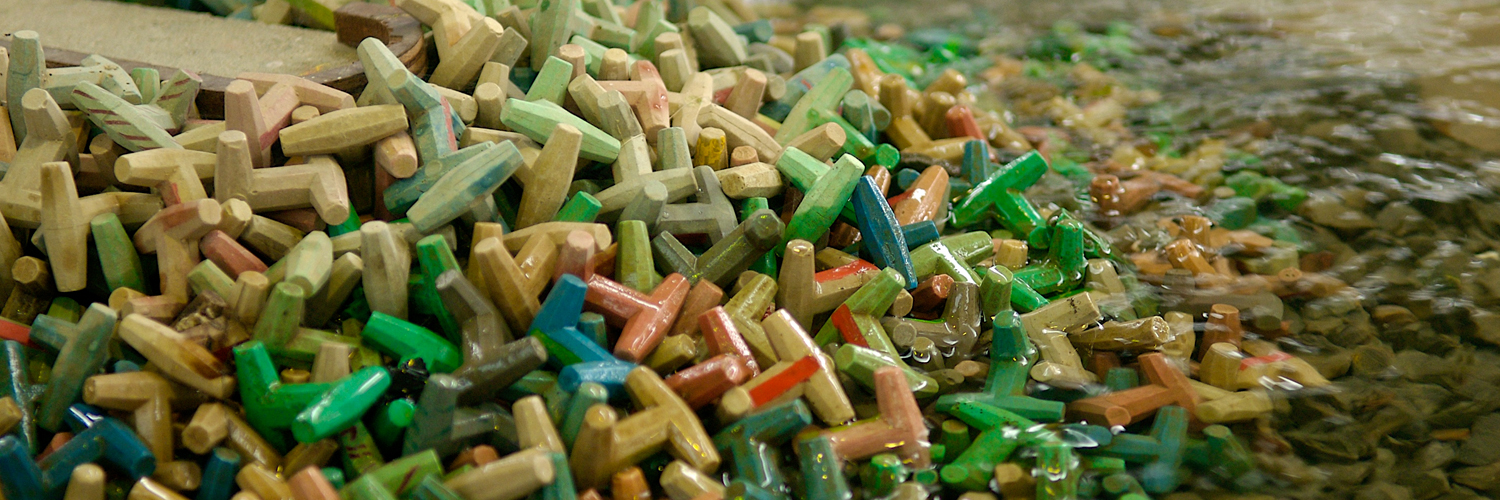
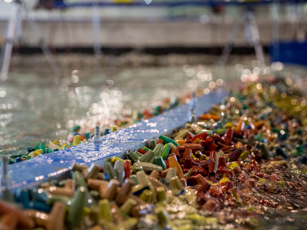
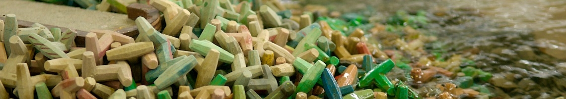
Slope and breakwater stability
Slope stability is measured using photography as well as laser scanning and is measured by identifying displaced armour units (concrete units used specifically for breakwaters; examples include Dolosse, Xblocs and KOLOS units). Scale units are manufactured using identical materials to ensure the properties are the same. In addition, the underlying rock for the model is sourced from a quarry producing similar rock as the rock used in the actual construction and graded at the laboratory, again to ensure that the properties are the same. For laser scanning, the Riegl VZ400 3D laser mapping scanner is used with accompanying software.
Services
Using these competencies, the laboratory can provide the following capabilities to clients:
- 3D wave agitation studies.
- 3D breakwater stability and wave overtopping studies.
- 3D moored ship response studies which include passing ship studies.
- 3D vessel grounding studies.
- Quasi-3D breakwater stability and wave overtopping studies.
- 2D breakwater stability and wave overtopping studies.
- 2D wave transmission studies.
Force and pressure measurement studies on caissons, floating walkways and various forms of slope protection.
Track record
The coastal and hydraulics laboratory has more than 40 years of experience in physical modelling for a range of local and international clients. The following selection of recent projects highlights the laboratory’s expertise.
|
Year |
Country |
Project |
Consultant |
Force |
Stability |
Wave |
Vessel Motion / Mooring Loads |
Overtopping |
Hydrodynamics & Flow Rates |
|
2023 |
Israel |
Haifa Port |
Jacobs |
|
X |
X |
|
X |
|
|
2023 |
RSA |
Louren’s River Diversion |
ASP Tech |
|
X |
|
|
|
X |
|
2022 |
Thailand |
Map Ta Phut Port |
PRDW |
X |
X |
X |
|
X |
|
|
2020 |
Mozambique |
Corumana Dam Spillway |
ASP Tech |
X |
X |
|
|
|
X |
|
2019 |
RSA |
Port St. John’s Tidal Pool |
PRDW |
|
X |
X |
|
|
|
|
2019 |
RSA |
Richards Bay breakwater repairs |
PRDW |
|
X |
|
|
|
|
|
2017 |
Saudi Arabia |
Confidential |
Royal Haskoning DHV |
X |
X |
X |
|
X |
|
|
2017 |
Chile |
Loma Larga |
PRDW |
|
|
X |
|
|
|
|
2016 |
Nigeria |
Dangote Breakwater |
CDR |
|
X |
X |
|
|
|
|
2016 |
RSA |
East London |
ECIJV |
|
X |
X |
|
X |
|
|
2016 |
Guinea |
Export causeway and breakwater |
PRDW |
|
X |
X |
|
|
|
|
2015 |
RSA |
Cape Town |
PRDW |
|
X |
X |
|
|
|
|
2015 |
RSA |
East London |
Stefanutti Stocks |
|
X |
X |
|
X |
|
|
2014 |
Peru |
Pampa de Pongo |
PRDW AVI |
|
|
X |
X |
|
|
|
2014 |
RSA |
Richards Bay |
TNPA RCB |
|
X |
X |
|
|
|
|
2013 |
RSA |
uMhlanga Tidal Pool |
eThekwini Municipality |
|
|
X |
|
|
|
|
2013 |
St Helena |
Rupert’s Bay |
PRDW |
|
X |
X |
X |
|
|
|
2013 |
Peru |
Pampa de Pongo |
PRDW AVI |
|
X |
X |
X |
|
|
|
2013 |
Australia |
Poseidon vessel grounding |
BHP Billiton |
X |
|
|
|
|
|
|
2012 |
Australia |
W Pilbara |
AECOM |
|
X |
X |
|
X |
|
|
2011 |
Qatar |
DohaEZ3 |
WP / AECOM |
|
X |
X |
|
|
|
|
2011 |
Australia |
Mackay |
Halcrow |
|
X |
X |
|
X |
|
|
2011 |
Myanmar |
Dawie Port |
Halcrow |
|
X |
X |
|
X |
|
|
2010 |
Australia |
Barrow Island |
JFA |
X |
X |
X |
|
X |
|
|
2010 |
Australia |
Port Hedland |
Baird |
X |
|
X |
X |
|
|
|
2010 |
Australia |
Dampier Port |
URS |
|
X |
X |
|
X |
|
|
2010 |
Qatar |
Port of Doha |
WP |
|
X |
X |
|
X |
|
|
2010 |
Georgia |
Port of Poti |
Royal Haskoning |
|
X |
X |
|
X |
|
|
2009 |
UAE |
Ras Al Akhdar |
WSP |
|
X |
X |
|
X |
|
|
2008 |
UAE |
Khalifa Port |
Halcrow |
X |
X |
X |
X |
X |
|
|
2008 |
Seychelles |
St Annes Zilwa |
WSP |
|
X |
X |
|
X |
|
|
2008 |
Georgia |
Port of Poti |
DMC |
|
X |
X |
|
X |
|